光照模型
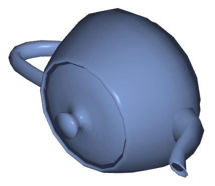
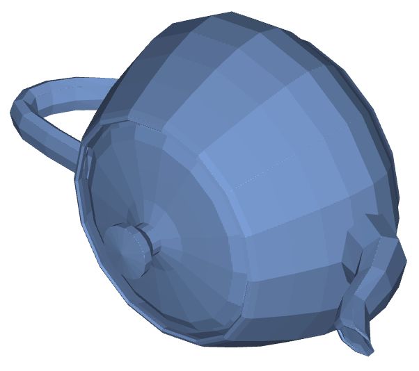
如果世界没有光影效果,那么我们看到的所有3D物体都是平面的,下面给出一个例子来模拟这种情况,您仅仅可以分辨出几何的外轮廓,但看不到它的立体效果。
只有当我们定义了几何表面对光照的不同反应效果,比如镜面反射、漫反射,使得几何表面分布着不同的光强度,这样我们才能像现实生活中那样快速识别出物体。
我们提供的Material库中将这些光照模型封装成材料,这样可以避免开发者直接和繁琐的着色器编码打交道,可拿来即用。下面我们以phong Material为例,来看一下它的光照效果是如何实现的,以及开发者如何使用它。更多的材质效果,您可以从我们的API文档中了解到。
Phong Lighting Model
冯氏光照模型(Phong Lighting Model)是一个相对现实世界而言作了简化的光照模型,它包含了三个分量:环境(Ambient)、漫反射(Diffuse)和镜面(Specular)光照
环境光照(Ambient Lighting)
即使在黑暗的情况下,世界上通常也仍然有一些光亮(月亮、远处的光),所以物体几乎永远不会是完全黑暗的。为了模拟这�个,我们会使用一个环境光照常量,它永远会给物体一些颜色。
把环境光照添加到场景里的方法非常简单,我们用光的颜色乘以一个很小的常量环境因子,再乘以物体的颜色,然后将最终结果作为片段的颜色:
漫反射光照(Diffuse Lighting)
模拟光源对物体的方向性影响(Directional Impact)。它是冯氏光照模型中视觉上最显著的分量。物体的某一部分越是正对着光源,它就会越亮。
镜面光照(Specular Lighting)
模拟有光泽物体上面出现的亮点。镜面光照的颜色相比于物体的颜色会更倾向于光的颜色。
使用Phong Material
在工业研发设计软件中,我们经常使用的就是Phong材料,而且不会对光源的位置和颜色做特殊要求,因此我们在封装Phong材料时,默认光源是白光,而且它是处于屏幕前的位置,您在使用这个材质时,只需要定义物体本身的颜色属性或者添加纹理贴图。
下面给出了一个具体的例子,这里我们先定义一个teapot几何,然后定义Phong材质。我们提供了三个接口,phong_color、phong_texture、phong_cube_texture,分别用于�指定颜色、纹理以及立方体纹理(用于环境映射效果)。
const geometry = await loadStanford('teapot');
const color = clr3(0.5, 0.6, 0.8);
const material = phong_color(color);
const node: JNode = {
    mesh: {
        primitives: [{ geometry, material }]
    }
};

const pass: JPass = Pass({
    background: background,
    camera: camera,
    node: {
        children: [node],
    }
});

const scene: JScene = {
    name: 'scene',
    passes: [pass],
};
您可以看到如下的效果:
除了phong模型,还有其他的一些光照模型,比如flat(color)。它的效果如下:
更多复杂的光照效果
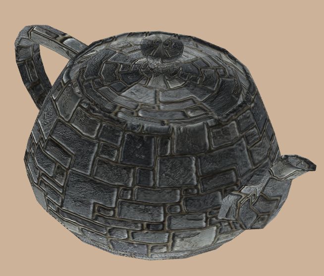
这里我们想要编写一个专门用来模拟凹凸材质的着色器,来帮助大家更深入地认识如何通过编程来实现真实的光照效果。
由于物体表面是凹凸不平的,那么��该物体的材质所使用的着色器中,在计算光照效果时,需要考虑表面的凹凸纹理属性。当然,这也要求您在几何的顶点信息中添加每个顶点处的表面法向和切向向量。
const geometry: JGeometry = {
    vertices: {
        positions: positions,
        normals: normals,
        texCoords: texCoords,
        tangents: tangents
    },
    indices: triangles,
    boundingBox: boundingBox
};
下面我们给出了可计算凹凸材质的光照效果的着色器:
const vs = `#version 300 es
in vec3 positions;
in vec3 normals;
in vec3 tangents;
in vec2 texCoords;

uniform mat4 modelViewProjectionMatrix;

out mat3 vLocalSpace;
out vec2 vTexCoord;

void main() {
    vec4 position = modelViewProjectionMatrix * vec4(positions, 1.0);

    vTexCoord = texCoords;
    vec3 normal = normalize(normals);
    vec3 tangent = normalize(tangents);
    vec3 bitangent = cross(normal, tangent);
    vLocalSpace = mat3(normal.x, normal.y, normal.z,
                    tangent.x, tangent.y, tangent.z,
                    bitangent.x, bitangent.y, bitangent.z);
    gl_Position = position;
}`;

const fs = `#version 300 es
precision mediump float;

in vec2 vTexCoord;
in mat3 vLocalSpace;

uniform mat4 modelViewMatrix;
uniform sampler2D texture0;
uniform sampler2D texture1;

const float ambientCoff = 0.2;
const float diffuseCoff = 0.7;
const float specularCoff = 0.1;
const float shininess = 7.2;

out vec4 fragColor;

void main() {
    vec4 color = texture(texture0, vTexCoord);
    vec4 normalColor = texture(texture1, vTexCoord);
    vec3 localNormal = normalColor.rgb * 2.0 - vec3(1.0);
    vec3 normal = vLocalSpace * localNormal;
    vec3 viewDirection = vec3(modelViewMatrix[0][2],
                            modelViewMatrix[1][2],
                            modelViewMatrix[2][2]);
    viewDirection = normalize(viewDirection);
    float nDotV = abs(dot(normal, viewDirection));
    float lightIntensity = ambientCoff +
                            nDotV * diffuseCoff +
                            specularCoff * pow(nDotV, shininess);
    color = vec4(color.rgb * lightIntensity, 1.0);
    fragColor = color;
}`;
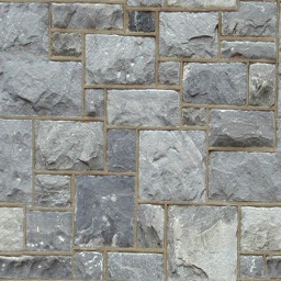
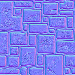
在最后,我们需要给出物体表面的贴图信息,包含两张贴图,一张是材质的颜色分布,一张是材质的法向分布。
const material: JMaterial = {
    program: {
        vertex: vert(vs),
        fragment: frag(fs)
    },
    states: {
        depth: Depth({ enabled: true }),
        texture0: Texture(image0, Sampler2DRepeat()),
        texture1: Texture(image1, Sampler2DRepeat()),
    }
};
image0和image1贴图分别如下:
最后,您可以看到几何体表面的材质是凹凸不平的,当您旋转相机时,效果会更加明显: