Understanding Material
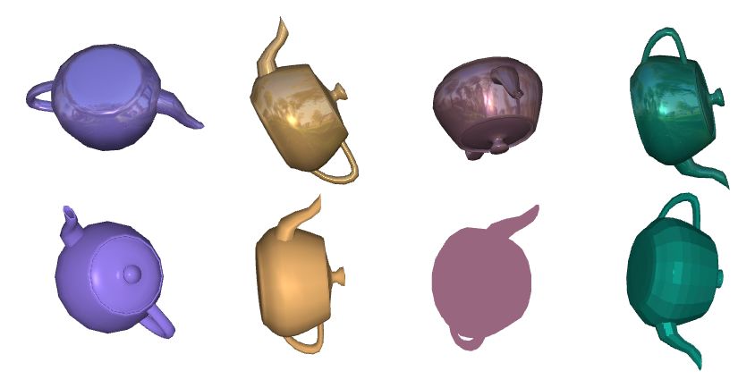
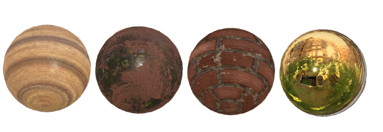
Materials define the surface appearance of objects, including their color, shading, textures, and more. Rendering engines use material properties to calculate how light interacts with objects, ultimately generating realistic images. Examples include surfaces of different colors, reflective materials that mirror the surrounding environment, bumpy brick textures, wooden surfaces with small dents, or metallic materials with rust.
In this section, we will discuss the following topics:
- Defining Materials: Learn how to define materials in ORE Core.
- Material Properties: Understand how to pass material properties to shaders using parameters.
- Shaders: Dive deeper into how shaders use material properties.
- State Bindings: Learn how to bind state parameters when rendering materials, which influence WebGL's primitive processing and the final rendering result.
Let’s start with a simple example to understand how materials are defined in ORE Core.
Defining Materials
A material consists of three main components:
- Program: Shader programs that define how 3D models are transformed into pixel distributions on the screen. Two types of shaders are used: vertex shaders and fragment shaders.
- Parameters: Uniform material properties required by shaders, such as material color, transparency, etc.
- States: State parameters, such as depth testing, blending, and texture mapping. These will be introduced in later sections.
Here’s an example to help you understand how these parameters are defined:
// Define the vertex shader
const vs = `#version 300 es

// Input geometry vertex data, transforming vertex coordinates to clip space
in vec3 positions;
in vec3 normals;

out vec3 v_normal;

uniform mat4 modelViewProjectionMatrix;
uniform mat3 normalMatrix;

void main() {
    gl_Position = modelViewProjectionMatrix * vec4(positions, 1.0);
    v_normal = vec3(normalMatrix * normals);
}`;

// Define the fragment shader
const fs = `#version 300 es
precision mediump float;

// The base color "color" of the material is used when shading fragments
uniform vec3 color;

in vec3 v_normal;
out vec4 fragColor;

float headLight(vec3 normal) {
    float nDotV = abs(normalize(normal).z);
    return float(0.4) + nDotV * float(0.6) + float(0.15) * pow(nDotV, float(50.0));
}

void main() {
    float lightIntensity = headLight(v_normal);
    fragColor = vec4(color * lightIntensity, 1.0);
}`;

// Define a material
const material: JMaterial = {
    program: {
        // Specify the vertex shader and fragment shader for this material
        vertex: vert(vs),
        fragment: frag(fs)
    },
    parameters: {
        // Specify the material's color
        color: clr3(0.8, 0.35, 0.1)
    },
    states: {
        // Enable depth testing
        depth: Depth({ enabled: true })
    }
};
Shaders
WebGL provides various shaders for rendering, which are essentially independent programs that transform inputs into outputs. Shaders are written in the GLSL (OpenGL Shading Language) and are independent of one another, communicating only through their inputs and outputs.
In material rendering, we use two types of shaders: vertex shaders and fragment shaders. In the example above, we’ve already seen the basic source code for these shaders.
Here’s the structure of a typical shader:
#version version_number
in type in_variable_name;
in type in_variable_name;

out type out_variable_name;

uniform type uniform_name;

int main()
{
  // Process inputs and perform some graphical operations
  ...
  // Output the processed result to the output variable
  out_variable_name = weird_stuff_we_processed;
}
In the vertex shader, input vertex attributes such as positions, normals, and texture coords are declared. In some cases, additional attributes like colors may also be declared. The vertex shader outputs the predefined variable gl_Position and can declare other output variables such as v_Normal or v_TexCoord. The main function in the vertex shader performs transformations of vertex attributes from 3D space to screen coordinates.
Shaders can pass variables between stages using matching input and output variable names. In the subsequent fragment shader, a color output variable must be declared. The fragment shader calculates the final color output for each pixel.
Parameters
We can assign values to variables directly in the shader program or pass them from the CPU to the GPU through our application. The latter is typically achieved by declaring a uniform parameter. Uniforms are global, meaning they must be unique within each shader program object and can be accessed by any shader at any stage. In the example below, we define a uniform parameter color for the material:
const material: JMaterial = {
    program: {
        // Specify the vertex shader and fragment shader for this material
        vertex: vert(vs),
        fragment: frag(fs)
    },
    parameters: {
        // Specify the material's color
        color: clr3(0.8, 0.35, 0.1)
    },
    states: {
        // Enable depth testing
        depth: Depth({ enabled: true })
    }
};
State Parameters
Materials can also bind a series of state variables to enable or disable certain states or define how states are used, controlling WebGL to perform desired operations. Below is a brief introduction to various states.
Blending
Blending is a technique used to achieve transparency in objects. A transparent object’s color is a combination of its own color and the colors of objects behind it, blended with different intensities.
Depth Testing
When depth testing is enabled, WebGL compares the depth value of a fragment with the contents of the depth buffer. If the test passes, the depth buffer is updated with the new depth value. If the test fails, the fragment is discarded.
Stencil Testing
Stencil testing operates based on the stencil buffer. By updating the stencil buffer during rendering, we can achieve interesting effects. After a fragment shader processes a fragment, the stencil test determines whether to discard the fragment based on other objects already drawn in the scene.
Texture Mapping
Texture mapping is essentially a 2D image (or, in special cases, a 1D or 3D image). The pixel values in the image can represent real material colors or other surface properties such as reflectivity or bumpiness, adding rich surface details to models and making them appear more realistic.
Face Culling
Face culling discards fragments that are not visible before they enter the shader, saving significant resource calls. We can tell WebGL which faces are front-facing and which are back-facing by the winding order of the vertex data.
Polygon Offset
In 3D rendering, depth conflicts can occur, causing fragments to flicker or fight for visibility. Polygon offsetting slightly adjusts the depth value of fragments, creating tiny gaps between them, ensuring they can be distinguished in the depth buffer.